01
Displacement control and generalized reactions
The two examples illustrate the same displacement-control principle with two different generalized quantities: a prescribed rotation with a reaction couple in Example 1, and a prescribed translation with a reaction force in Example 2.
Under force control, a generalized force or couple is prescribed and the corresponding displacement or rotation is obtained. Under displacement control, the displacement or rotation is prescribed and the generalized reaction becomes an additional unknown. A Lagrange multiplier enforces the kinematic constraint and adds one equation and one unknown to the finite element system.
02
Example 1 — initially curved compliant mechanism
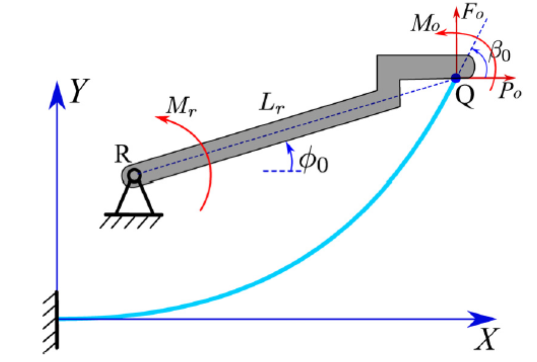
The compliant mechanism contains a parabolic flexible beam and an approximately rigid crank. The flexible beam has a rectangular cross-section , is made of brass, and has Young's modulus . The crank length is , its initial angle is , and its endpoint is . The flexible-beam centerline is the parabola when coordinates are expressed in millimetres.
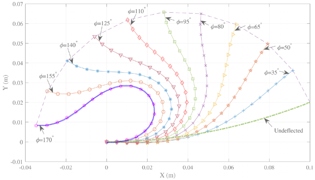
The deformed configurations reported by Chen et al. [1] are shown together with the finite element result. The thick blue curve is obtained with the Updated Lagrangian MATLAB program.
03
Lagrange-multiplier formulation
To impose the crank rotation, a Lagrange multiplier is introduced to enforce the kinematic constraint. The prescribed quantity is the rotation increment
The associated multiplier represents the generalized reaction required to satisfy this constraint; in the present problem this generalized reaction is the crank couple , with its sign determined by the adopted convention. If is the nodal rotation to which the constraint is applied, the unconstrained total potential energy is:
and the constrained potential becomes:
Here is the global nodal displacement vector and is the global nodal load vector. For the isoparametric Timoshenko beam element,
Stationarity with respect to the multiplier imposes . The supplementary potential-energy term is:
and gives the supplementary residual vector and tangent matrix:
These quantities are assembled into the global residual and tangent stiffness matrix by the standard finite element procedure. For nodes, the constrained problem therefore has unknowns instead of ; the additional unknown is .
Displacement control provides as a function of the imposed crank rotation . On a monotonic equilibrium branch, this relation corresponds to the inverse representation of the force-controlled response .
04
Example 1 — program and results
The MATLAB program adds one equation through neq=neq0+1, with ; therefore . The rotation of node 1 is constrained, and S(neq) is the additional generalized reaction. In gen.m, Ang=pi is the total prescribed rotation increment of , not the initial crank angle. Since , the final angle is .
ip=[3 neq];
K(ip,ip)=K(ip,ip)-[0 1;1 0];
F(ip)=F(ip)-[S(neq); S(3)-Ang/nstep];
Each Updated Lagrangian load step starts from the known configuration . The term S(3)-Ang/nstep enforces the prescribed crank-rotation increment during the current step, thereby obtaining configuration from configuration ; S(neq) is the Lagrange-multiplier unknown representing the generalized reaction required by the constraint.
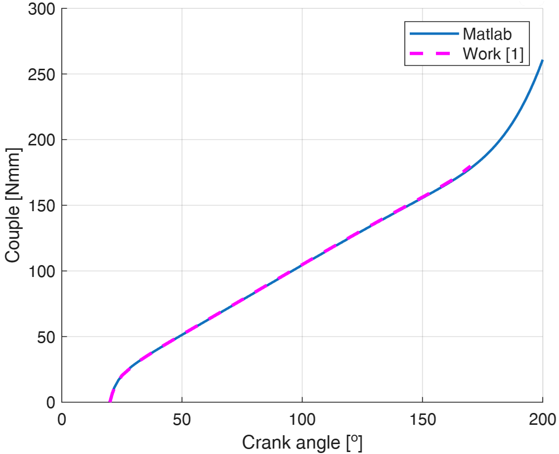
The diagram shows the dependence of the applied couple on the crank angle . The results obtained with the MATLAB program agree with those reported in [1].
Animation — prescribed crank rotation
05
Example 2 — fully compliant inverter
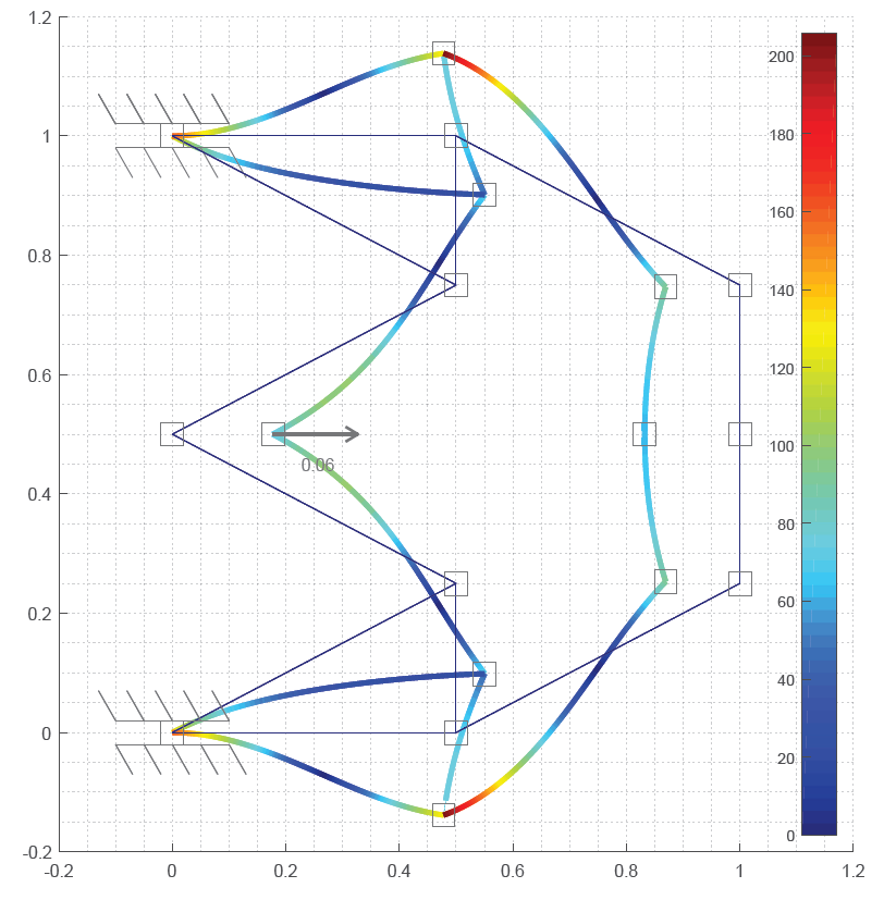
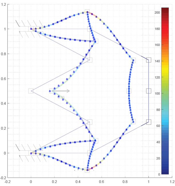
The second example is the fully compliant inverter analyzed by Turkkan and Su [2]. The nodal coordinates are shown in Figure 4. Every link has an in-plane thickness and an out-of-plane thickness of . The material has Young's modulus .
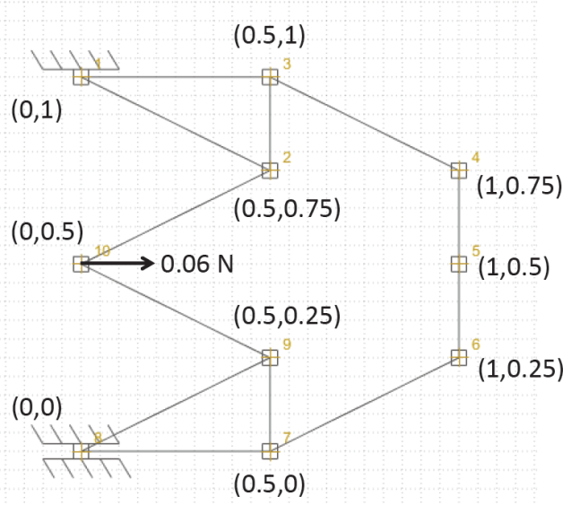
The geometry diagram indicates a representative horizontal force of . In the present displacement-controlled computation, the horizontal displacement is imposed instead and the corresponding reaction force is obtained.
06
Example 2 — prescribed translation
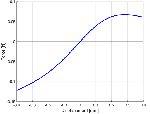
In this example, displacement control is applied to the horizontal displacement of node 2. The prescribed horizontal displacement is enforced by means of a Lagrange multiplier. The associated multiplier represents the generalized reaction required to satisfy the imposed displacement; in this case, the generalized reaction is the horizontal force . Thus, the computation provides as a function of the prescribed horizontal displacement.
The input data set disp=-0.4 mm, while dof=4 identifies the horizontal displacement degree of freedom of node 2. The Lagrange multiplier, representing the horizontal reaction force, is stored in S(neq), where .
dof=4;
ip=[dof neq];
K(ip,ip)=K(ip,ip)-[0 1;1 0];
F(ip)=F(ip)-[S(neq); S(dof)-disp/nstep];
The current Updated Lagrangian step starts from the known configuration . The term S(dof)-disp/nstep enforces the prescribed horizontal displacement increment for that step, while S(neq) is the Lagrange multiplier—the horizontal reaction force required to satisfy the constraint.
07
Example 2 — results and comparison
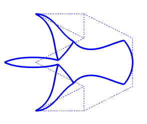
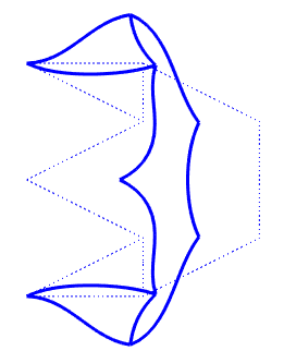
The force–displacement curve and the two end configurations describe the complete prescribed-displacement path.
Animation — negative displacement branch
Animation — positive displacement branch
Figure 6 compares the deformed mechanism reported in [2] with the finite element results obtained in this section. The blue points are the computed nodal positions and are retained exactly as supplied.
08
MATLAB packages
Each example is distributed as a separate, self-contained package containing five MATLAB files and one README.
Both packages were executed in MATLAB R2026a. Example 1 reached a final crank angle of and a reaction couple of . Example 2 reached the prescribed displacement and a horizontal reaction of .
09
References
- G. Chen, F. Ma, G. Hao, and W. Zhu, Modeling Large Deflections of Initially Curved Beams in Compliant Mechanisms Using Chained Beam Constraint Model, Journal of Mechanisms and Robotics, 11(1), 011002, 2019. ResearchGate access.
- O. A. Turkkan and H.-J. Su, A general and efficient multiple segment method for kinetostatic analysis of planar compliant mechanisms, Mechanism and Machine Theory, 112, 205–217, 2017. ResearchGate access.